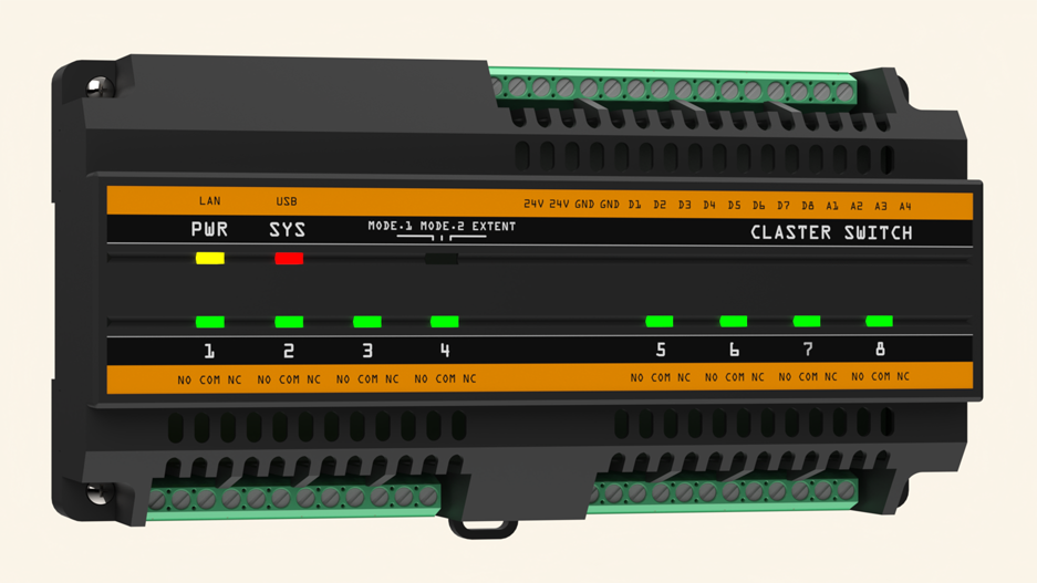
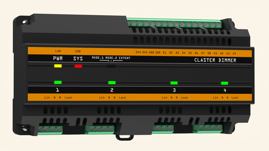
It is a set of DIN-rail modules that control lighting and other circuits over your home network. They connect by Ethernet and work with your existing controller, or on their own.
Working prototype. Claster has run nonstop in a my home for six years. It is not yet certified and is not currently for sale. If you’d like to see it become a product…
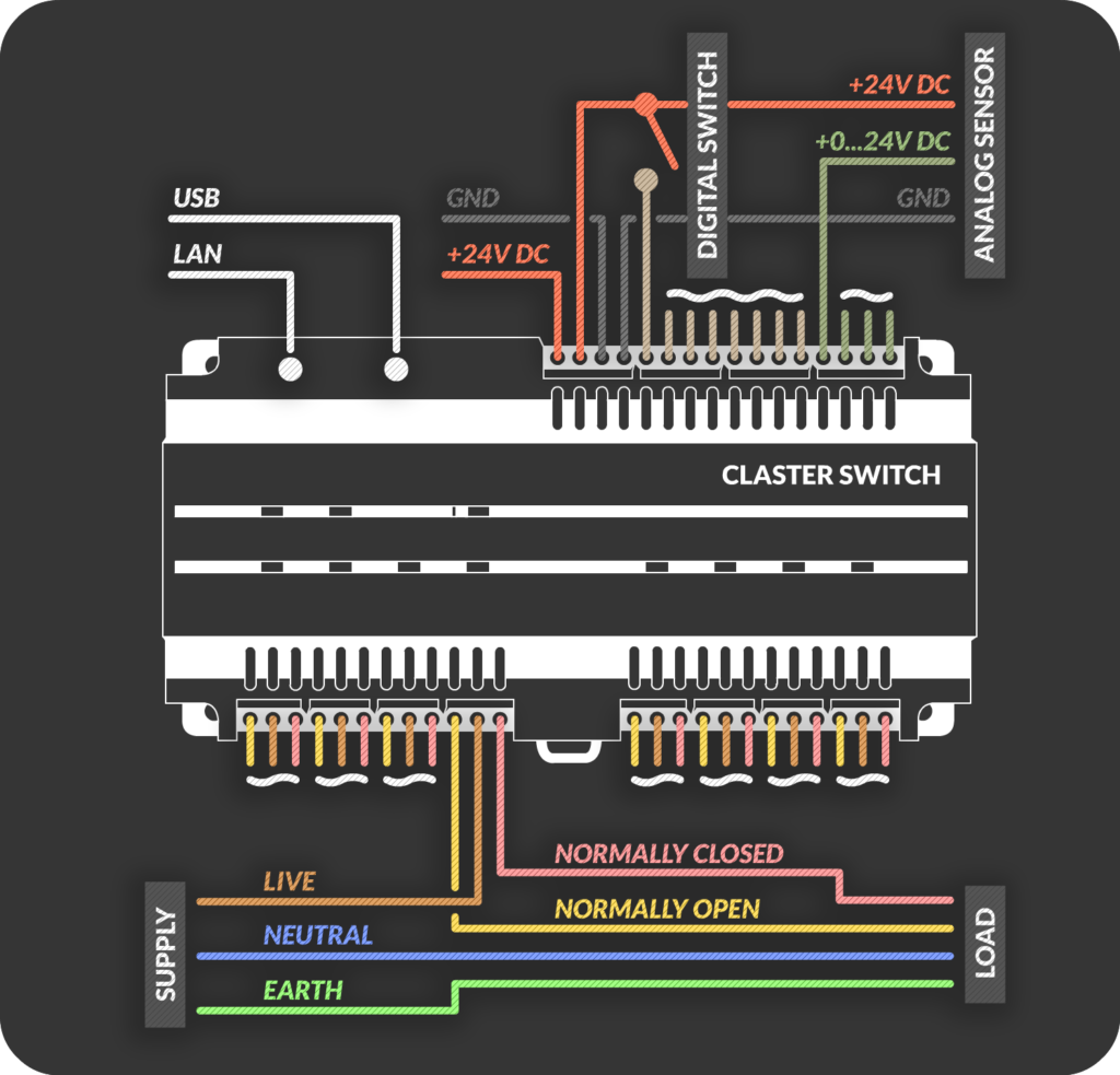
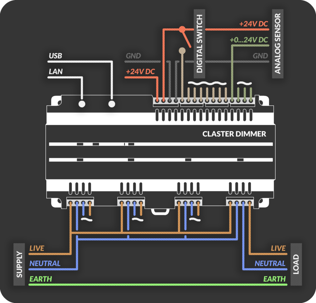
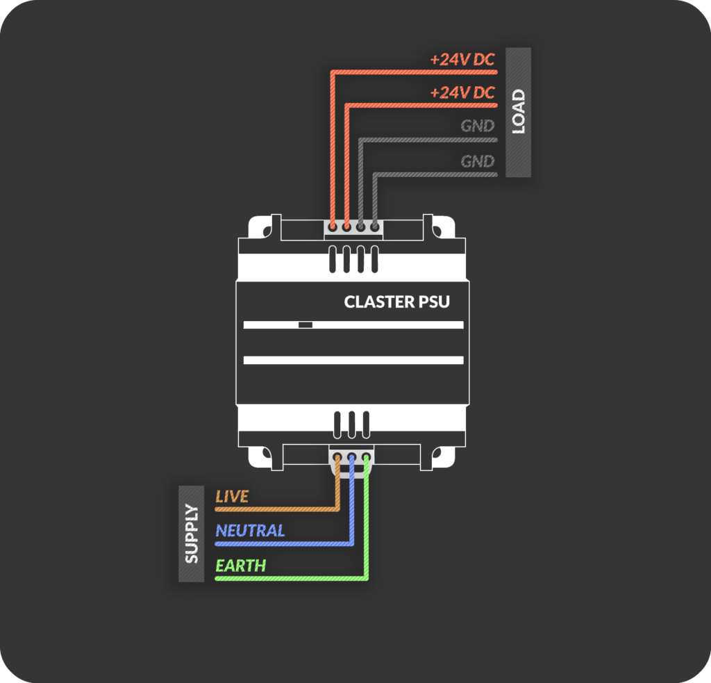
Connect the 24 V power supply to the module. Two LEDs (orange and red) light up.
Connect the module to your network with an Ethernet cable.
The module gets an IP address automatically. When it succeeds, the red LED turns off and the module is ready.
To find the module’s IP address, check the list of connected devices in your router. Other details are on the label on the side of the module. Ready-made setup templates for popular systems will be available in the download section, so no programming is needed.
Connect your switches
Wire your wall switches and push buttons to the digital inputs. The analog inputs (0 to 24 V) take low-voltage dimmer controls or any sensor with a 0 to 24 V output.
Whenever a switch is pressed or a value changes, the module sends a message to your controller over the network. Your controller always knows which module and which input was used, and it can also ask any module for the current state of its inputs and outputs at any time, for example after a restart.
Choose how it works
Controller mode Your controller is in charge. It receives every press and change, and sends commands back to switch outputs. Use it for scenes, schedules and smart-home logic.
Push-button mode (standalone) Works on its own, with no controller needed. Built for momentary switches: press one and its light turns on or off straight away. If a controller is connected, the module still reports everything to it.
Switch mode (standalone) Also works on its own, with no controller needed. Built for latching (regular on/off) switches: the output follows the switch. If a controller is connected, the module still reports everything to it.
Push-button and switch modes run inside the module, so your lights keep working even without a controller.
Works with what you already have
Claster communicates with simple UDP messages on your local network, so any system that can send and receive UDP can use it. The full command reference is open and documented, so you can integrate Claster with your own system easily.